Nashville SE 20 – Modifications after 18 Months
After 18 months of service the power amplifier design underwent some minor modifications:
Active cooling:
Summer 2018 was really hot over here in Dresden and temperatures in our apartment were above 35°C at some
days (no air conditioning). That was around 10°C above the regular room temperature on which I had based my
calculation for the amplifier heat sink size. Hence active cooling would provide a comfortable safety margin and
probably also improve the longevity of the power transistors. I experimented with several cooling fans and finally
the SAN ACE 120 silent fan (Model 9s1212l4011, Sanyo Denki) proved to be really low noise and almost inaudible
when operated at 9V DC (operating voltage range according to the datasheet is 7V to 13.8V DC). Voltage is provided
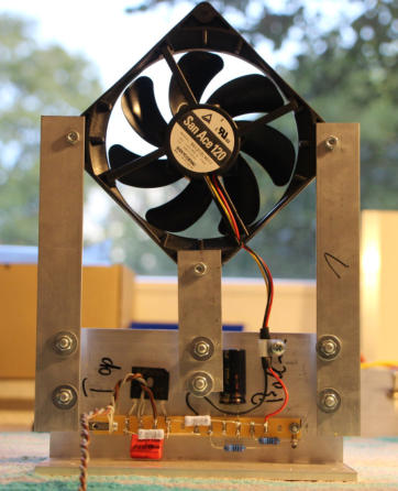
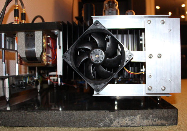
from the two free heater terminals of the LL1649 mains transformer. Figure 1 and 2 show the cooling device with
the mounted fan and the power supply.
Fig. 1 and 2: Assembly of the cooling device and cooling device mounted at the power amplifier.
Increasing Transistor Idle Currents
Active cooling also allowed to increase the idle current of the power transistors from 460mA to 500mA although
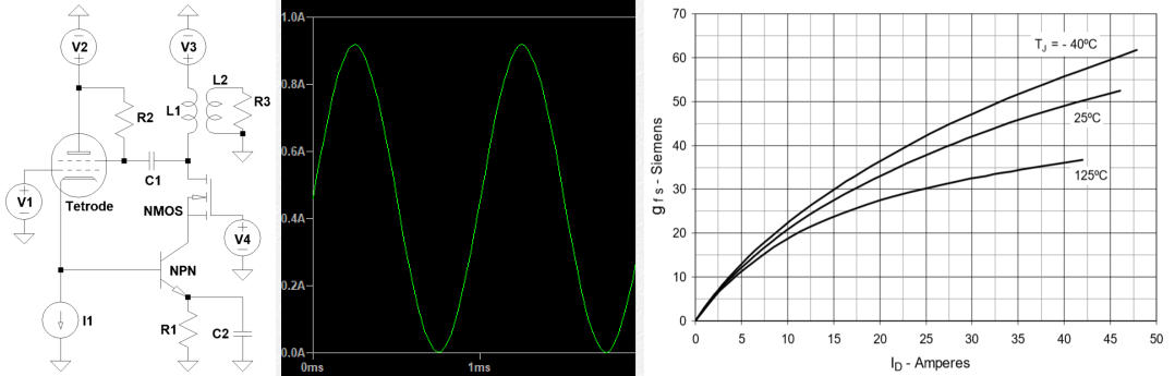
460mA is the limit recommended for the LL1693 output transformer. However, if negative current peaks of the
audio signal approach zero at maximum level (fig. 3a and b) the transconductance of the cascoding transistor also
approaches zero (fig. 3c). Thus at points of zero current of both the BJT and the MosFet the circuit is somehow in an
undefined state. Shifting the idle current from 460mA to 500mA leaves a headroom of 40mA at the low end. On the
other hand at maximum currents the transformer might be driven slightly into core saturation.
Fig. 3a to c: Current swing of the power transistors at maximum level power and transconductance of the MosFet
as a function of its drain current
Increasing the idle current was done simply by adding a 500Ohm resistor in parallel to the other emitter resistors of
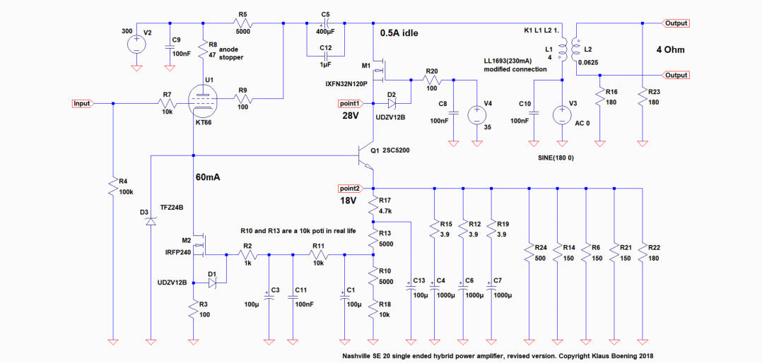
the BJT (see schematic in fig. 5 below).
Adding an Anode Stopper to the KT66
Generally cathode followers are prone to oscillation. To prevent unwanted oscillation the KT66 power tetrode was
already provided with control grid stopper (10k) and a screen grid stopper (100Ohm). Just as an additional safety
measure and with respect to good engineering practice I added a 47Ohm anode stopper to be really on the safe
side concerning parasitic oscillation. Figure 5 shows the revised schematic of the power amplifier.
Fig. 5: revised schematic of the Nashville SE 20 power amplifier (click on schematic to enlarge)
super triode, vinyl, audio, analog, single ended, SE, power amplifier, hybrid, tube, KT66, 6SN7, ECC88, Mosfet, Lundahl, MC phono stage, preamplifier, MM, MC, moving coil, moving magnet, LL1693, LL1667, LL9226, LL1933, RIAA, folded
cascode, 2CS5200, MAT12, 2N3810, LL1660S, IXFN32N120P, balancing amplifier