Nashville SE 20 - Some basic Math on the
SuperTriode Concept
Basic calculations require one component to start with.
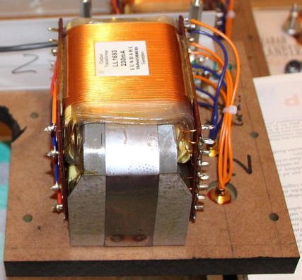
I chose the output transformer as the most crucial
component. For the project the single ended version
of a Lundahl LL1693 seemed to be a good match
regarding quality, pricing, technical data and size (fig. 1).
The SE version of the 4.5kg transformer has a core
air gap of 450µm. Recommended idle current is
230mA with all primary windings in series. Primary
inductance is 16H. With a secondary connection B
(4Ohm, see Lundahl datasheet) the reflected primary
impedance is 1kOhm.
Inherent Output Power Limit
The recommended transformer idle current of 230mA allows a theoretical current swing from 0mA to 460mA peak
to peak (p-p). According to I
2
* R = P a simplified power calculation neglecting transformer losses reveals a
maximum output power of
(0.23A / sqrt2)
2
* 1000Ohm = 26.45W ≈ 26.5W
(equation 1)
which is the inherent output power limit, not too much but fairly above the requested minimum of 20W. Hence I
stayed with the LL1693 for further calculations. By the way, the push-pull version of the LL1693 is capable to handle
around 300W output power.
Output Voltage Swing (fig. 2)
Considering a „worst case“ estimation of 30W output power
and 1kOhm primary impedance the power output voltage
swing p-p at the primary coils according to U
2
/ R = P is
sqrt 2 * (sqrt(30W * 1000Ohm)) * 2 ≈ 490V p-p
(equation 2)
With an estimated minimum residual voltage of 100V
across the triode the power supply voltage would have
to be around
100V + 490V / 2 = 345V ≈ 350V
(equation 3)
Thus the maximum voltage peak expected to be at the
plate is
100V + 490V = 590V
(equation 4)
Adding a comfortable safety margin (speakers unintentionally
disconnected) the circuit components should withstand
900V to 1000V peak voltage, nothing special for a tube but
pretty much for a transistor.
Power Dissipation
From the above equation 3 and a given idle current of 0.23A the total power dissipation is 350V * 0.23A = 80.5W.
Assuming an idle current of 30mA for the triode and an idle current of 200mA for the transistor plus a plate /
collector voltage of 350 V power dissipation at the plate will be 10.5 W and power dissipation of the transistor will
be around 70W. 350V and 200mA idle current must be within the DC safe operating area of the transistor with a
comfortable safety margin. This will rule out BJTs because of their inherent secondary breakdown. That leaves
power MosFets. Power MosFets meeting the specifications above are available for instance the IXFN32N120P.
However, these MosFets are designed for industrial high power switching applications. They are quite non-linear at
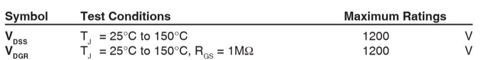
low drain currents and have large gate capacitances. Below some data on the IXFN32N120P are discussed (fig. 3).
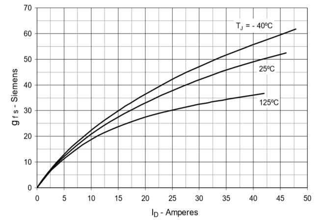
Fig. 3: Maximum ratings and transconductance of the IXFN32N120P.
At low currents transconductance g
m
is a linear function of I
drain
. Estimated transconductance g
m
at 230mA is around
0.6S. U
max
of the IXFN32N120P is 1200V, P
d
is 1000W, gate capacitance C
iss
is 21nF. With a load resistance of 1kOhm
the effective (or Miller) capacitance is
C
M
= C
iss
* ( 1 + gain) = C
iss
* (1+ (gm * 1000)) = 0.021µF + (1+(0.6*1000)) = 12.62µF (equation 5)
12µF (!) dynamic input capacitance is difficult to drive without compromising high frequency response even without
the essential gate stopper resistor. Thus the IXFN32N120P or similar devices with even lower gate capacitances are
hardly suitable for a SE power amplifier according to the SuperTriode concept.
Core Magnetization
The SuperTriode configuration (fig. 4) suffers from an additional flaw: Even at large signals the plate current
remains almost constant. Thus in a single ended design the current through the tube just magnetizes the output
transformer‘s iron core but does not contribute to the output power. If 200mA idle current are assumed for the
transistor, the inherent power limit calculation from above equation 1 drops to 20W and will be less if transformer
losses are taken into consideration.
Conclusion
With regard to the required minimum specifications of
the transistor it may be concluded that the SuperTriode
concept as illustrated in figure 4 is not suitable for SE
power amplifiers if an output power above a few watts
is requested despite its beauty and simplicity.
On the other hand the concept is far too fascinating to be
discarded . . . .
Fig. 1: Lundahl LL1693 output transformer
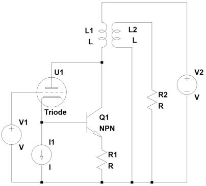
Fig. 4: SuperTriode concept.
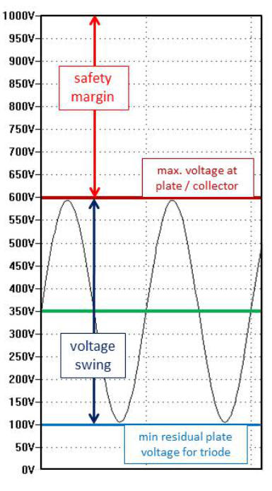
Fig. 2: estimated voltages at the plate /
collector of SuperTriode circuit
discussed

super triode, vinyl, audio, analog, single ended, SE, power amplifier, hybrid, tube, KT66, 6SN7, ECC88, Mosfet, Lundahl, MC phono stage, preamplifier, MM, MC, moving coil, moving magnet, LL1693, LL1667, LL9226, LL1933, RIAA, folded
cascode, 2CS5200, MAT12, 2N3810, LL1660S, IXFN32N120P, balancing amplifier