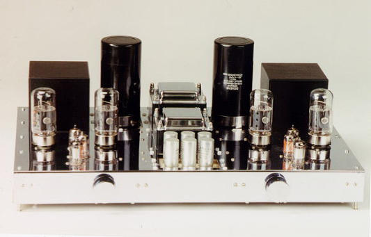
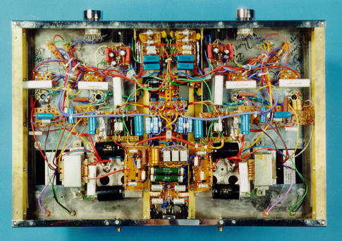
Tube Power Amplifier 2 x 50W
Please note: The pictures show an older version of the amp rather than the schematic. This version used EF 86 in the phase
splitter stages similar to the QUAD II design and 6550A output tubes.
Input stage
The amplifier comprises four stages, input stage, phase splitter, driver and output stage (see schematic). Input
tube is a UHF twin triode ECC 81 (12AT7), operating in single-ended differential mode. System I is a cathode
follower that feeds the signal into the cathode of system II. Hence the input has very high impedance, determined
only by the volume control (or grid resistor). Input capacity also is very low, for there is only static capacitance but
no dynamic capacitance (Miller capacitance) as usual in common cathode triode circuitry. Besides cable
capacitance, the preamplifier output only “sees” the static capacitance of grid/plate C
GA
and grid/cathode C
GC
respectively.
System II is a differential amplifier working with the input signal from the cathode follower at its cathode and local
negative feedback at its grid which is defined by two resistors of 270k and 68k. By shuffling these resistor values
the local NFB and thus the input gain can be adjusted. Main purposes of local NFB are enhancing bandwidth
(250kHz at -3db point in my application) and reducing adverse effects of aging or tolerances in tube data on
tonality and stereo image.
The cathode idle currents of the ECC 81 automatically set to a ratio of 4mA to 1mA due to plate of system I being
directly connected to the +rail ("through grip" effect). This is sonically advantageous. A cathode follower's distortion
is directly related to its current swing because internal plate resistance and transconductance of the tube change
with current. If the current of system I is substantially higher compared to system II, current changes with signal
and hence changes in internal plate resistance and transconductance are low. For similar reasons the cathodes are
coupled by a current source instead of a conventional resistor.
Current sources look like resistors of almost infinite resistance and still allow to keep currents high. The cascode of
the BF245 and BC548 build a "rock solid" current source with an internal resistance of several GigaOhms. The
BC548 can be considered a current source for the BF245.
Another advantage of the current source is an absolutely constant load at the +rail. The total current (I
AI
+ I
AII
)
across the two systems stays absolutely the same, no matter whether heavy bass or diminutive transients are run
through the input tube. Replacing the ordinary tail resistor by a current source gave a remarkable improve in
stability of tonality, stereo image and DDR (Downward Dynamic Resolution, as Allen Wright calls it in his very
remarkable tube preamp cook book). The serial regulator HIP 6300 reduces hum to almost zero. Serial regulators
normally should be banned from audio circuitry, but in this case in worked fine.
Phase splitter stage
The ECC83 (12AX7) converts the unbalanced signal into balanced signals. It works as a long tail phase splitter and
has the advantage of high gain, good frequency response and large voltage swings. Negatives are a poor balance
and the necessity to tweak the plate resistors for balanced voltage, if you do not use a current source!
For optimal symmetry the cathodes must be coupled by a stable current source instead of a tail resistor. Then the
current of the first system can only rise to the extent the current of the second system is lowered and vice versa. If
the current in system I increases by 0.01µA, the current in system II must decrease by 0.01µA. So the phase split
signals are forced to be perfect mirror images, depending only on optimum similarity of the anode resistors. And
again, you have the advantage of an absolutely constant load at the +rail. Differential amplifiers were always
considered less precise than single ended amps. From my experience differential amps with conventional tail
resistors are loose and they indeed loose signal detail because the circuit parameters can shift with voltage swing.
A good current source locks the total current down and differential amps become as precise as single ended amps.
The anode resistors of the 12AT7 are relatively high in value for good linearity at large signals. This is because the
KT88 beam power tetrodes are run in an anode/cathode coupled circuit similar to the QUAD II amps by Peter
Walker (the McIntosh circuits also look similar in the first, but they work differently). The voltage swings of the
phase splitter must cover the grid voltages necessary to drive KT88 plus the voltages that are fed back into the
KT88 by the cathode coils of the output transformers.
Driver stage
270 kOhm at the anodes of the phase splitter and low idle currents of 1.1 mA give a relatively high output
impedance of the 12AT7. Thus with respect to the low grid resistors of 68 kOhms at the KT88, cathode followers
were added in galvanic coupling for low impedance. The ECC82 (12AU7) was chosen, because it has acceptable
transconductance for low impedance and allows 180 volts between cathodes and heater. Again current sources
were chosen as load resistors at the cathodes for the reasons discussed previously. They allow the ECC82 to run at
idle high currents, but current swing is only depending on the tetrodes grid resistors of 68kOhms. With ordinary
tail resistors of 30kOhms and idle currents of 5mA the current swing would be between 3mA and 11mA at signals
of 80 volts peak to peak. With a current source the current swing is limited between 6mA and 8mA.
The MOSFETs IRF 830 can handle up to 500 volts and work very reliable. To dissipate their wattage, they are
mounted on small heat sinks. The gate resistors at the MOSFETs are essential to avoid RF oscillation. For the same
reason the ECC82 and KT88 have grid stopper resistors. The currents of the cathode followers are adusted to 5mA
by the source resistor of 2.4kOhm.
Output Stage
As already mentioned the KT88 tetrodes are run in an anode/cathode coupled circuitry (ACPP in the schematic
stands for anode-cathode-push-pull). This circuitry goes back to Peter Walker and is also used in the bigger Jadis
tube amps as far as I know. The trick is a local feedback from the plates into the cathode/grid loop. The voltage
controlled feedback grant the tetrodes characteristics similar to triodes with low impedance and low distortion
while maintaining their ability to high output power. With 430 volts at the plates the output power is 50 watts.
Contrary to ultra-linear stages the anode/cathode coupling allows free choice of optimum voltages at the screen
grids. Stabilizing the screen grid voltage at 370 volts gave further improvements in sonic performance in my
application. I tried the IRF 830 as regulator but I could not keep it from oscillating. So I used a BUT13 Darlington
transistor.
The plates of the KT88 dissipate around 30 watts. According to the data sheets the tetrodes should have a
minimum distance of 10 cm (4 inches) from each other to avoid picking up radiated heat from the neighbor tube.
The amplifier has a negative feedback loop from the secondary coil of the output transformer into the phase split
stage. In my experience NFB can be somehow compared with pharmaceutics. They have effects and they have
adverse effects. To achieve best benefit, you carefully have to adjust the dose and in some cases the best dose
may be zero.
However, the stability of the stereo image is very much dependent on an equal gain in both channels. Even the
smallest gain fluctuation blurs the image especially when it comes to the reproduction of depth. That NFB is the
best tool for stabilizing is often overlooked, despite the fact that everyone agrees on the importance of gain
stability. A tube amplifier is more prone to gain fluctuations than a solid state amplifier. Small movements of the
electrodes due to heating change the properties of a tube at least to some degree.
In my application a good compromise between woofer control, stability of the stereo image and vitality was
achieved with NFB between 10db and 12db. The capacitor was tweaked to 240pF by adjusting to best square wave
response at the output.
See schematic of the power source unit.
Back to top of the Page
Back to main Page
I built this tube amp back in 1994. It served me well until I replaced it in 2017 by
my new single-ended hybrid tube / solid state power amp.
super triode, vinyl, audio, analog, single ended, SE, power amplifier, hybrid, tube, KT66, 6SN7, ECC88, Mosfet, Lundahl, MC phono stage, preamplifier, MM, MC, moving coil, moving magnet, LL1693, LL1667, LL9226, LL1933, RIAA, folded
cascode, 2CS5200, MAT12, 2N3810, LL1660S, IXFN32N120P, balancing amplifier